Eeyore
-
Posts
1,152 -
Joined
-
Last visited
Recent Profile Visitors
7,880 profile views


Eeyore's Achievements
")
Rising Star (8/12)
105
Reputation
-
Keep trying, he’ll get there eventually😎
-
Get a "T" handled hex key and a length of string as a wrist strap for the outside. Small hex keys are difficult to hold and often dropped. You may occasionally encounter one of the more interesting things about working with stainless fasteners; their ability to lock up solid despite only being spun on by hand. Just have to shear or cut them off and try another one.
-
Have you bled all the radiators (and any other bleed points) before running the Webasto? You will need to leave the charging loop connected and turned on whilst bleeding the system; and the main domestic water pump switched on.
-
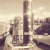
The blue arrow points to red knob for adjusting the pressure relief valve. These can sometimes stick/weep, so its worth checking that nothing is dripping from the pipe marked in red.

-
Thanks for the update. The forum software has an annoying habit of combining posts, and making it difficult to follow threads sometimes. I'm still curious as to why the header tank is there at all. Might as well remove it as its only taking up valuable space.
-
Not sure how repeating your self is helping us to help you. At least give us the picture I reqested 😎
-
Humour me please. You can get your hand all around the plastic "header" tank, and can't feel or see any pipe or hose connections? I would consider it very optimistic to use gate valves to achieve 100% seal regardless of actual function. You need to trace where these are connected. A new image of the gauge from slightly further back might be helpful.
-
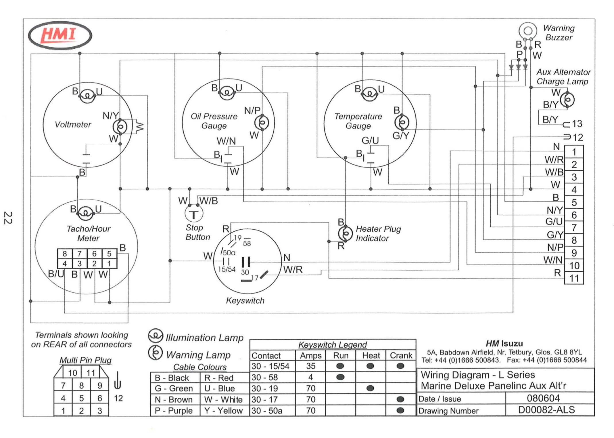
Rather depends on whether you have a currently non functioning gauge on the panel, or intend to fit a stand alone gauge. A photo of the panel would be helpful. The green/blue wire is for a gauge. (Some manufacturers only produce one wiring loom, and will have all the optional wires installed regardless.) Do you have the wiring diagrams?
-
 Wouldn't that be the grounding solenoid for the "insulated" return wiring harness?
 -
Morse control stuck in neutral?
-
It's also worth checking the spill (return to tank) pipework for damage/restriction. Has been known to create similar symptoms. The coolant pipe thing may be a red herring, there are a lot of incorrectly labeled images on the web.
-
I think the TNE engine has very small coolant hoses running to a temperature controlled advance unit. The later TNV certainly does. A blocked hose will leave the engine running in "cold start" position. Can anyone confirm?
-
A sliding mount for the secondary shaft bracket will work with the existing (primary) belts. A polyvee 6PK belt with a tensioner pulley running on the back of the belt will allow for a fixed relationship between the secondary drive pulley and alternator, and will provide additional wrap (belt contact) on the smaller alternator pulley.
-
Yes, I think David Macks idea will fit below the alternator. The intermediate shaft mounted on two bearing (on a suitable bracket). Both pulleys at one end for a forward facing alternator, or one each end for an aft facing alternator. Depends which gives the clockwise rotation required by most modern integral fan alternators.
-
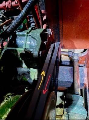
Is there much clearance at the back of the alternator? What is the direction of rotation? red or yellow arrow? Which 120amp alternator are you thinking of?