Trilby Tim
-
Posts
241 -
Joined
-
Last visited
1 Follower

About Trilby Tim

Recent Profile Visitors
5,482 profile views


Trilby Tim's Achievements
")

-
I'm currently going from Thorne to Sheffield, so if you want to have a look at it you could come and meet me somewhere along the route (or in Sheffield when I get there).
-
Yes, I did this time, 2 pairs on each clamshell. They were the last job and I did them at 8pm the night before it was due to be re-floated so didn't take any photos!
-
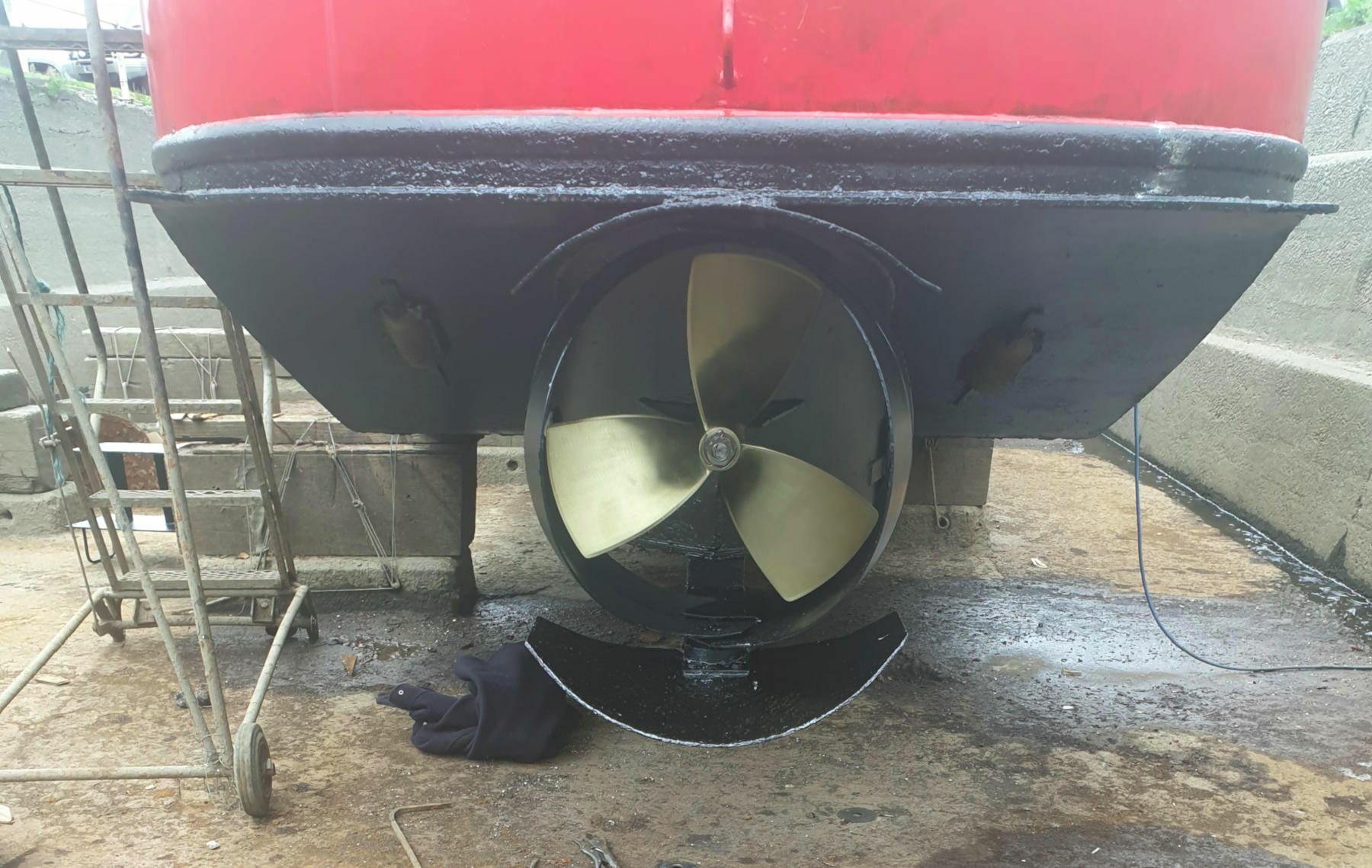
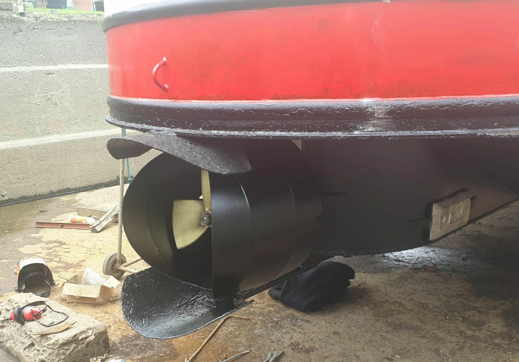
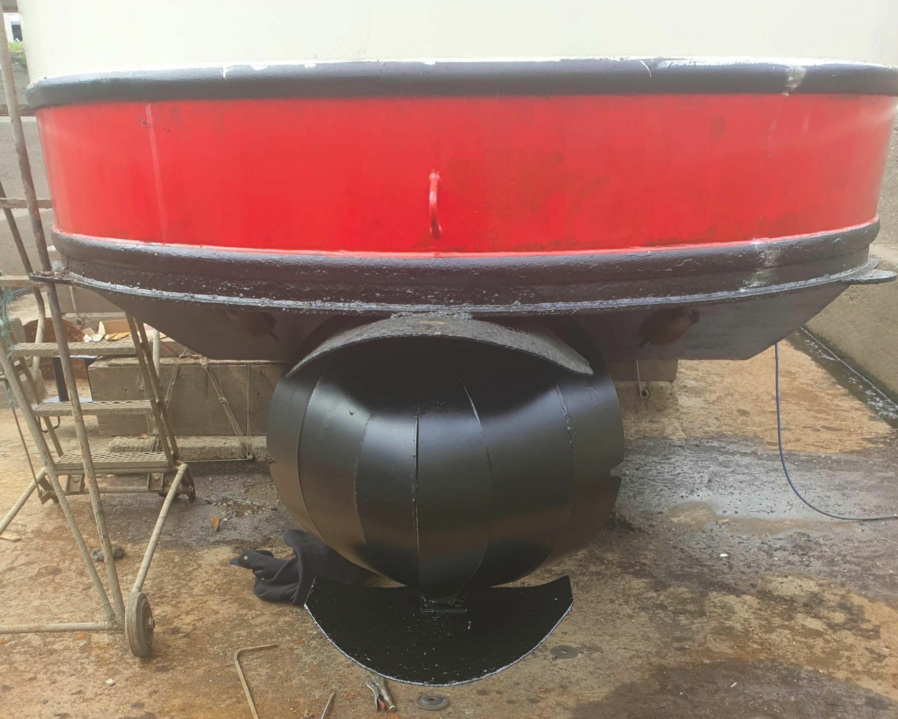
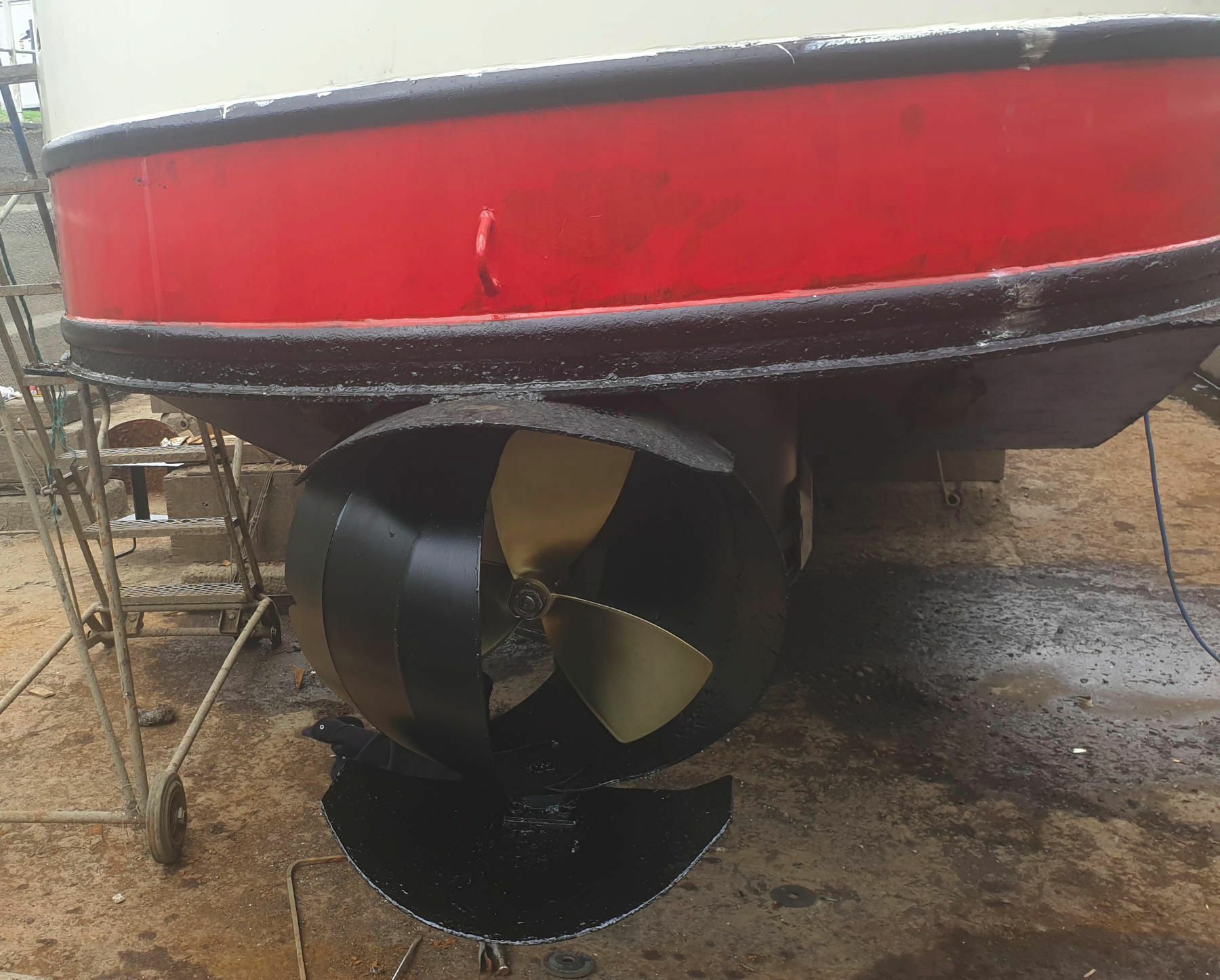
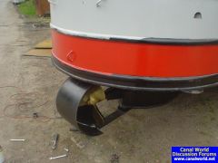
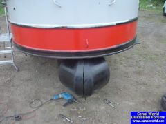
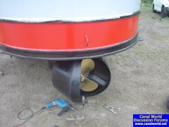
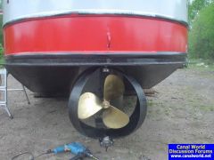
So, 10 years on and the latest instalment in the engineering vanity project known as fitting a kitchen rudder to a narrowboat! Earlier in the year I tried to take the boat out for a cruise but one of the rudder clamshells failed around the weld on the top. I think this was galvanic corrosion caused by the stainless steel shafts (at least as it runs in plastic bushes the shafts and rudder are isolated from the hull of the boat anyway). Actually the boat was still pretty controllable with only half the kitchen rudder (once I managed to remove the half that was now loose), probably about as manoeuvrable as a normal narrowboat. I did consider replacing the kitchen rudder with something simpler like a Kort nozzle, but basic stubbornness made me double down, design a new version of the rudder, get it made and fit it with a new prop and new gearbox. I attempted to use CFD to design it, but wasn't able to get very meaningful results so ended up using rules of thumb and intuition again. Got the new version fitted and the boat refloated a week ago and I have to say, it's pretty good, a definite improvement over the previous version. The boat stops very quickly, requires less force on the tiller to do it and it still spins on the spot or steers where you want it in forwards or reverse. It really is very manoeuvrable indeed. Still not perfect though, now it's introduced a directional instability into it in forwards (open) position, which is very annoying. The next time it's out the water I'll need to do more changes, although I'll probably just be able to do it by fettling this one with an angle grinder (remove area from in front of the pivot line) rather than making a whole new version. The new prop and gearbox are also a big improvement, it allows the engine to rev more comfortably and I don't get cavitation like previously, it just seems to grip the water and go. If anyone else is remotely tempted to indulge in engineering self-flagellation then I've made the whole design Open Source, so you can download it from here: https://gitlab.com/trilbytim/kitchen-rudder If anyone has any CFD skills and fancies a bit of a challenge then it could be a really interesting design problem. I've included my attempts in Sparselizard and OpenFOAM in the repo. It would be interesting to really optimise the shapes of those clamshells using CFD.

-
Actually it died after only a couple of months of running twice a day last winter. However they did exchange it without quibble and it's replacement is (touching wood while writing this) doing fine. Although obviously it hasn't had a huge amount of use over the summer, so the real test is still to come.
-
It's fitted and so far so good for operation. A few niggles with fitting, It wasn't delivered with a silencer which was sent later when I pointed out it was missing, there's no damper on the fuel pump despite the instruction manual describing one (I was told that it doesn't need one and never includes one, so why the instruction manual refers to it is baffling). It's shipped with a plastic bodied fuel filter that would fail a BSS test if you fitted it (I didn't, mine is fed through the same filter as the engine; apparently this can cause problems for the heater if you try and run heater and engine at the same time but I can't imagine why you'd want to do that, it can also cause problems for the engine if you don't have a solenoid shut off valve on the feed to the heater, but I do so I've never had any problems with this set up). Electrics reasonably simple, the supplied wiring loom connects to all the Mikuni's connections. The old Mikuni switch and timer/thermostat connect and switch it on and off but the LED on the switch doesn't work so you can't be sure what it's doing and won't get any fault codes without the new MV panel. This isn't a massive problem as I never used the thermostat anyway (cycling the Mikuni on and off was always seen as a problem so I just set it to be on or off on the timer, never thermostatically cycling) and the new timer that comes with the MV is much neater and slicker so I'll use that instead. I'll remove the old Mikuni one when I get round to it. It fired up immediately first time and every time since and seems to give good heat output. I've been using it most days for a couple of weeks and so far so good. It's pretty quiet (a little quieter than the Mikuni I think) since I fitted the silencer. The real test will be whether it keeps it up though!
-
I did actually get a PM from someone that hadn't had one long but reported so far so good. I think it's less a case of the install being "good" or "bad" it's more about being lucky enough that your requirements and use pattern happen to match what the heater is happy with. I think they have a really narrow operating window, if you hit it then they're great, but many (maybe most?) people don't, which is why they deservedly get so much flak. I've often heard that they need to be worked hard, and that's probably true, but I'm pretty sure that in my case the problem was that I was working it too hard. I have the underfloor heating system so when I switch it on it's trying to heat over a tonne of concrete, that's definitely working it hard! I fitted data logging equipment to it and found it was hardly ever getting up to a good temperature even after over two hours on. That's why I hacked the control system to force it to heat up faster. That did actually work pretty well, last winter with the hacked control system was the best it ever performed, and I had plans to improve it further. But now the air motor has blown and replacement is a silly price it just felt like throwing good money after bad. The MV Hydro 5 has brushless motors on the air and water pump, so should never need replacing and bizarrely are cheaper if you do have to replace them than the inferior MX40 items. Also I like that the MV has a glow pin rather than a glow plug so hopefully won't keep blowing all the time, it does seem like they've learnt something from the mistakes of the MX40. So even if I do have to hack this one to make the bloody thing work properly, at least I'm starting from a better base.
-
I've decided to bite the bullet and try it, can't be any worse than the MX40! Maybe if I hadn't had anything better to do with my time and I'd completely replaced the control system I could have made it work properly, but it really was a case of trying to make a silk purse out of a sow's ear. The MX40 is now out and being sent back, so hoepfully a new MV Hydro 5 will soon be back in it's place and in theory should just be a drop in replacement.... We'll see, I'll let you know how it goes, and if it continues to go for more than a few hours in a row!
-
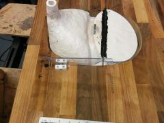
Thanks for the comments. I do already have a job, and a lot of other projects taking up my time so don't have any interest in producing them. Quite happy to make it 'open source' though, happy to send the CAD on request (although the CAD was good for working out the general concept, the design changed quite a bit as I actually built it!). And if anyone wants the separett plastic bowl as a pattern for moulding from I'm happy to sell it on. The urine can be disposed of down the Elsan, the solids can be buried. The picture of the trapdoor is taken looking from the underside, it's upside down. The trapdoor falls open under gravity. It's pushed closed by an arm on each side (made out of clear polycarbonate plastic, so it doesn't show up that well in the photo!) that pushes on a pin that produces from the edge of the trap. The end of the arm that pushes on the pin is curved to a profile to allow the trapdoor to swing through a full arc and provide a sensible mechanical advantage, it took a bit of trial and error to get that curve profile right. The arm is pivoted on the pair of white blocks. The arm is sprung loaded on one side and pushed by a dowel on the other side. So when you sit on the seat, the seat pushes down the dowel (which passes throught he walnut worktop) and the dowel pushes the arm down (up looked at in the photo) out of the way of the trapdoor which swings open under gravity. When you get off the seat the springs are powerful enough to push the arms back up, pushing the trapdoor closed and the dowels back up. There's a matching arm mechanism on each side as one wasn't strong enough to hold the trap closed on it's own with the weight of the seat resting on it. Clear?
-
No, there is still a fan, inside the chimney that runs up inside the cupboard behind. Even if you evaporate the liquids you still have to let the water vapour out. There's nothing that new here, besides possibly the carousel arrangement and the mechanism for the trapdoor, mostly it's just a case of putting ideas together and building it properly!
-
Hi Peter, yes I've just designed build and fitted a new toilet. I put the photos up but then got distracted before I had any chance to write an explanation! I've described it now: http://www.canalworld.net/forums/index.php?showtopic=79409
-
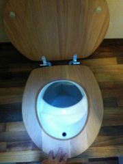
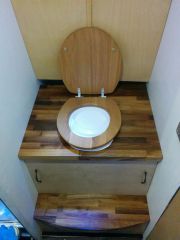
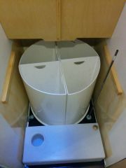
When I built my boat I fitted her with a Sun-Mar Excel composting loo. I've used it for 5 years with mixed experiences. The principle seems good but the practice disappointing, in particular the build quality of it. It feels plasticy and flimsy, basically a bit cheap and nasty. However, of course it isn't cheap, it's was actually very expensive!! Various bits have broken and fallen off it over the years. Most recently the back panel has cracked meaning that the gears to rotate the drum jumped when you tried to turn it, so you couldn't properly. So I'd had enough of it, it was time to replace it. I looked again at what was on the market. The Enivrolet is similar to the Sun Mar in that it mixes lquids and solids. which I wanted to avoid after the Sun Mar. There's also been bad experiences of this reported on this forum, and without a UK importer there's no chance to see before you buy, so no way of knowing if it's any better constructed than the Sun Mar. And again it's really expensive. I looked at the Airhead. This actually seems to be pretty well designed and built compared to everything else on the market. However it's really small, it has so little capacity that it'll need emptying frequently before things have had a chance to properly decompose. To be fair it's not designed for continuous use, would probably be fine if only used occasionally. I also looked at the Villa. The principle was fine, I liked the trapdoor that opened when you sat on it and I liked the collecting bin that rotated by a small angle each time you sat on it. But again it feels cheap and flimsy (and at £600 plus options it ain't cheap!). Also I have a fairly large space available from where the Sun Mar stood, the Villa would only take up some of that space and would waste the spare space. So I decided to build from scratch using the principles I most liked from the others but adapted to fit my application and properly engineered. So the design needed to be: -Urine separating rather than mixing -Large capacity to use the entire available space and maximise the time to compost before emptying -Look, feel and actually be solid and robust! -Use a standard toilet seat (not a flimsy plasticy one) and preferably a ceramic bowl. A ceramic bowl was unfortunately unpractical to make (I don't have any experiences or facilities to work with ceramic). So instead I moulded one using a Separett plastic bowl as a pattern. I surfaced it with chemical resistant polyester resin blended with ground marble powder which gives a similar appearance to ceramic (like most baths, shower trays, etc) backed up with a thick layer of glass fibre/polyester. My initial plan was to have 4 round collecting bins for solids sitting on a carousel. One would be in use at a time and would be rotated round by a small angle on each use (like the Villa). When one was full, the carousel would be rotated by a quarter of a turn to use the next one. When all four were full, the first would be emptied and used again and so on. However I decided that this was probably unnecessarily complex, wasted space between each bin and wasted height by having to have each bin on an indivdual turntable as well as the overall carousel. So I went for a simpler, more space efficient design with 4 quadrant shaped bins on the carousel. Each individual bin doesn't move on the carousel, you just fill one, and rotate to the next when all are full empty the first and carry on. It's large capacity, each one of the 4 bins is greater capacity than the single bin on the villa. The design looked like this: Putting it into practice, I got the carousel and bins fabricated by a local company to my drawings. I had a coil of 8mm pipe to pump hot water though laid under the Sun Mar to heat it and aid evaporation so I kept that and put a steel plate over it to form the base of the new toliet. The walls became the insides of the new toilet. They shouldn't get damp in there, but I painted them with yacht varnish and sealed all gaps with silicone to be on the safe side. I then screwed some little wheels to the bottom of the carousel to allow it to turn: I screwed a couple of fixed castors to the walls to act as guides for the carousel and put a shaft with another wheel to turn the carousel and a handle on the top of the shaft. The castors are spring loaded to press the carousel against the drive wheel. I've put in a 25 litre urine tank under the step, here's the workings of it: I had some block board walnut worktop and birch ply left over from the bathroom units so used this to make the top, front and step. I designed a trap door mechanism that opens when you press down on the seat (e.g. sitting on it): Here's a picture of the finished unit (with a standard oak seat): And with the seat pressed down (trap open): So it's just about done. It looks good and is built like a brick sh*thouse! Now needs a few years use to determine whether it works and is robust!
-
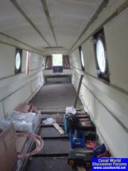
The DIY fit out of our shell.
-
-
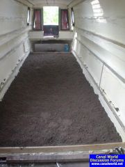
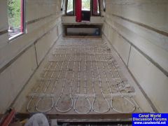
I like it, it's in the front half of my boat, in the showeroom and bedroom area. A couple of inches of sprayfoam over the baseplate, pipes clipped to that and then concreted over and the floor's the same height as the rest of the boat. Everyone carries loads of ballast in the bottom of the boat anyway, it makes sense to use it as thermal mass to store heat. I don't think it wastes excessive amounts of heat into the water, it seems to hold heat reasonably over night. Also on the occasions the canal has frozen up I've not noticed any difference in the rate the ice melted around the front of the boat (with underfloor heating) to how it melted round the back (without underfloor heating), and I was looking out to see if I could see a difference.
-
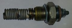
Hi, has anyone had any experiences, good or bad, with the MV Hydro 5 diesel heater that's replaced the Mikuni MX40? The air motor on my MX40 has now died Incidentally this isn't as a result of my hacking it, I hadn't actually got as far as hacking that bit of it, so it was only running in the way Mikuni intended, so it is just plain old unreliability. It's £140 for a new motor! The MX40 has been constant trouble and unreliable. However I do really like the convenience of it when it does work! So I would like to still have a diesel heater. I don't know whether to get a new motor and continue with my work of hacking the control system to try and make it more reliable or whether to cut my losses with it and replace it. Probably by doing this: http://www.ebay.co.uk/itm/MV-Hydro-5-Water-Heater-Conversion-for-Mikuni-MX40-/171858420377?hash=item28038f6299 The MX40 has now been discontinued by Mikuni and they're promoting the MV Hydro 5 instead. I don't like the idea that by buying a MV Hydro I'm basically paying Mikuni more money to fix a problem they created by building the unreliable MX40! However I'd be willing to swallow my pride and do that if I thought it would actually work properly. At least spares for it are cheaper, it's a brushless motor that in theory should run for ever, it's a glow pin rather than the hopeless glow plug that blew all the time (although if the pin does fail then it's more expensive to replace than the plug), so it does sound an improvement. I'm not particulary keen on the idea of a Webasto or Eberspacher either as from reading comments on this forum they don't sound any better than the MX40! Does anyone have an MV fitted?
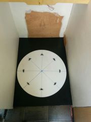
-
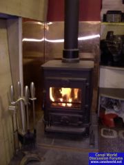
Sorry, not been on this forum in ages. The underfloor heating is nice, and still working without problem (touch-wood) after 5 years, which is a lot more than can be said for the Mikuni that I often use to heat it! The wood-burning stove doesn't really put enough heat into the water to be very effective at heating the UFH, unless you really stoke it up heavily! However the stove alone does do enough to take the chill the chill off the floor even though it doesn't really heat the bedroom/showeroom that effectively. Running the engine is very effective at heating the UFH and gets the rooms nice and warm. When the Mikuni is actually working then this also heats the UFH very effectively. If the UFH is properly warm (i.e. has been heated by the engine or the Mikuni, not just by the stove) when I go to bed then it will still have some warmth in it when I wake up. I've put tiles on it as you can see in this image below. The more insulation you have between the heating and the air the worse the performance of the UFH will be, so tiles best, wood or laminate OK, thin carpet bad, thick carpet hopeless. One point if you're having a shell built: I recommend getting lower pieces of angle section floor bearers welded into the floor in the area you're fitting the UFH. I have 2" angle across the floor all the way through. These are ideal if you're screwing a wooden floor to them and have to fit ballast underneath, but in the case of the UFH they get in the way and I wish I had had 1" used in the UFH area. I had 2" of sprayfoam put over the floor in the UFH area, so where the angle irons were there were really big lumps! This then meant that laying the pipes was hard and when the concrete went down it couldn't be constant thickness and was really hard to get level. In the end I had to put more floor levelling compound over the top of the concrete, and then the tiles on top of that. The extra floor levelling screed also helped ballast the boat better as she was a little high at the front when she went on the water. The floor in the UFH area has ended up about the same height as the floor in the rest of the boat despite the difficulty though. I was worried that a lot of heat would be wasted into the water, but this doesn't appear to be the case. The UFH seems to hold it's heat well, as I say it's often still warm in the morning even when there's been nothing heating it overnight. Also on the occasions when the canal has been frozen over I've not noticed the ice melting around the front (UFH area) of the boat any differently to around the back (not UFH area), so I don't think much heat is being lost into the water.